![[top]](img/top2.jpg)
The Binary Clock Project
Just what is a binary clock? Instead of using numbers like 1,2,3,4 etc
to display the digits it show the numbers in binary format. Unlike
standard numbers which are base 10, binary numbers are base 2. They
only have two numbers. A 1 and a 0.
base 10: 153 = (1 x 10 x 10) + (5 x 10) + ( 3 x 1)
base 2: 101 = (1 x 2 x 2) + (0 x 2) + (1 x 1)
Here is a small table:
0000 = 0
0001 = 1
0010 = 2
0011 = 3
0100 = 4
0101 = 5
0110 = 6
0111 = 7
1000 = 8
1001 = 9
Learn more about binary in the wikipedia.
Time is typically written like HH:MM and thus has 4 digits. So my
clock will have a row for each digit.
0001 = 1
0001 = 1
0011 = 3
1001 = 9
The time is 11:39.
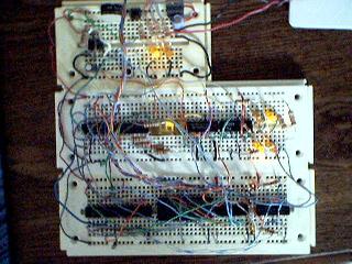
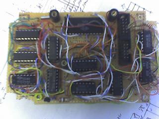
This is the prototype. This was actually built way back in 2003. Part of the goal was to use logic chips I already had in my junk drawer. If I were to do it all over again in 2018 I would do the whole thing with an ardunio nano module and a ds323 real time clock module. It would be so much simplier. Anyway, the whole project just sat on a shelf until 2007 when I finally got back to it. In the original circuit I intended to have a 7-segment display to use 5 of the LEDs to show tick every 10 seconds. The LED got removed due to space limits but the logic chip is still there because it is still needed to divide the pulse down to 1 sec.
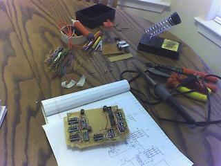
5/8/2007 - Construction began a week or two ago. A little over half of the sockets on the main board are done. It is going much slower than I thought. It takes time to do point to point wiring. That was actually one of the big reasons it took so long to start the actual building. I had planned to etch a printed circuit board. But the drawing just became too complicated and I was going to have to do a lot of wiring anyway since it was only going to be single-sided. I also decided it was going to be too many holes to have to drill.
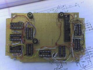
5/15/2007 - Things are starting to get a little messy. I should have done more of the wires closer to the board.
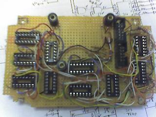
5/21/2007 - Main board is done! I had to solder the one chip because the 24-pin socket I had ordered was to small. I was not going to delay things (or put any more money into this thing) to try to order the right socket.
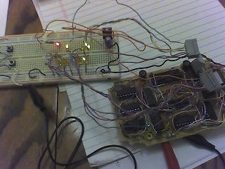
Time to test it. If it did not work then there would not be any
need to build the display board.
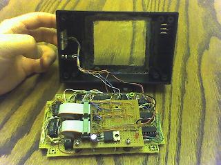
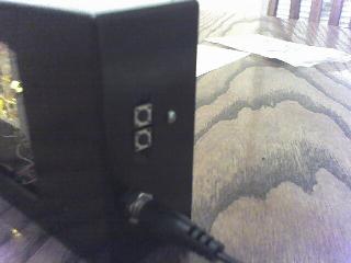
6/6/2007 - Everything is pretty much done. The window has been cut is the case along with hole for the switches and power jack. And added a few holes to allow heat to escape. The 7805 5-volt regulator dissipates a lot of heat. I had do away with the heat sink due to space limitations.
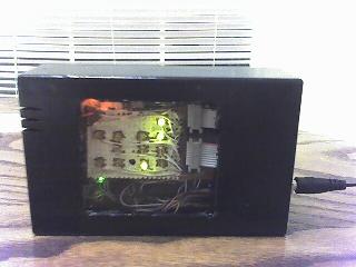
6/9/2007 - Finally done! I decided to paint the display board white so the lights would show up better. I wish I had thought of that in the beginning because it would have been so much easier to have painted the board before I soldered anything to it. It was a pain painting around the lights. I do wish I had soldered the red LED (PM indicator) is little lower. The green LED blinks once every second. Top two rows represent the hours. Bottom two rows are the minutes. Each row is a digit. This shows 11:02PM. Switches are used to set the hours and minutes. One flaw: The one for the hours is on the bottom and the minutes is on the top. It would have made more sense if the order matched the order of the lights on the display board. Oh well.
Date: Summer 2007